Previous topic
Next topic
2.4.1. Buildes v2014.0.4.3-alpha
This Page
Quick search
Enter search terms or a module, class or function name.
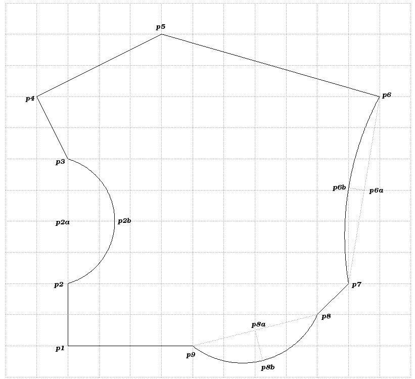
In this tutorial, we will copy an existing outline based on the coordinates provided as shown in Figure 2D Outline with Coordinates. The figure is laid out on a 1 x 1 meter grid which provides the coordinates.
2D Outline with Coordinates
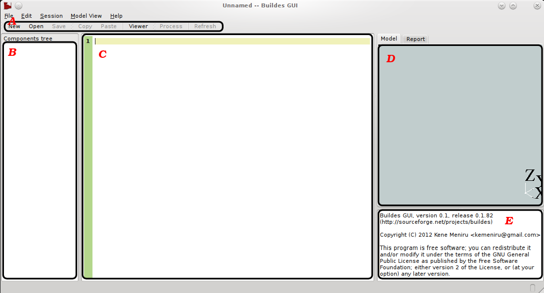
We also assume that you have downloaded and installed buildes (see Installation). Fire-up buildes GUI (in linux type ./buildesui.py & at the shell prompt while in the bin directory into which you pulled buildes). When the program is running, click on “Viewer” to switch to the IDE mode. You should see something similar to Figure Buildes GUI in IDE mode. Additional information on the commands used in this tutorial can be found in the Reference Pages section.
Buildes GUI in IDE mode
The area labeled “A” shows the toolbar. “B” is where a tree representing the relationship between the parts being modeled is shown, “C” is the editor area where you enter the description of the objects you want to model, “D” is the model view area where the shape of the modeled objects will be displayed and “E” is the message area where buildes will provide additional information about what it is doing as well as information on the objects selected in the tree area.
As we want to create only mark objects, the following are the barest minimum commands needed to set-up for creating and visualizing marks in buildes. Enter these commands in the empty editor area. All commands are case-sensitive:
from buildes import *

designer("First-Name Last-Name", "011-000-0000")
entryCoords(CAD)

saveSession()
When finished save your session file. Make sure the “Save” command in the toolbar is grayed to show that your work has been saved. Save after typing each line to be sure not to lose your work.
The first line from buildes import * imports buildes tools that we need to create mark objects. The second is a command that provides the details of the designer. This must be provided before the user can be able to save and visualize any data using buildes. The full syntax is: designer(“name-of-designer”, “phone”, “email”, “role-in-design”, “office-name”). The “name-of-designer” and the “phone” parameters are required.
The third command is not really a requirement but makes it possible to choose a preferred or appropriate coordinate entry system. We will be using the internal modeler and viewer for buildes which is based on pythonOCC, a python binding for the Opencascade library. This provides a CAD interface so it would be beneficial if we use a CAD coordinate entry system.
The final command instructs buildes to save any objects created so we can visualize them in the GUI. This command must be the last command in the session file otherwise you may not see all the objects you have created.
To create our first mark enter the following line before the saveSession() line:
lineMark("p1-p2", 2000, 0)
This line tells buildes that we want to create a line mark called “p1-p2” that is 2000 mm long and inclined at 0 degrees (which means it is going vertically upwards). We know this because from Figure 2D Outline with Coordinates, we can tell that the distance between p1 and p2 is 2000. We also know that the angle between the two points is 0 degrees (NOTE: This is unlike typical drafting systems which designate horizontal lines from left to right to be at 0 degrees.) With this information we can create the first line mark directly using the “lineMark” command. The syntax is: lineMark(“name-of-mark”, length, angle). At this time the line mark has been created but not placed yet in the design. If you process your file now you will not see anything in the model view area. To place this line mark in the design add the following line:
put("p1-p2", (0, 0, 0))
With this command we ask buildes to place “p1-p2” using the absolute coordinates provided. By using the name “p1-p2” we are telling building to use the first point on the line mark. All line marks (all objects in buildes actually) have at least a first, middle and end points that can be accessed with “b”, “m” and “e” consecutively. Typically you will combine an object’s name with the desired point to designate the point for manipulation such as “p1-p2_m”, but when no manipulation point is provided, buildes assumes the first point.
The “put” command is a versatile one along with its companion “offset”. They are the only commands that you can use to place objects in the design. This version of “put” places the named object at the provided coordinates without reference to any other object in the design. This is usually typical when placing the first object. Based on our selected entry coordinate system, (0, 0, 0) designates x=0, y=0 and z=0. So far our session file looks like this:
from buildes import *

designer("First-Name Last-Name", "011-000-0000")
entryCoords(CAD)

lineMark("p1-p2", 2000, 0)
put("p1-p2", (0, 0, 0))

saveSession()
From now on when asked to enter a command, enter it just before the saveSession() line with a leading and ending space just as we have entered the lines for creating and placing the first line mark.
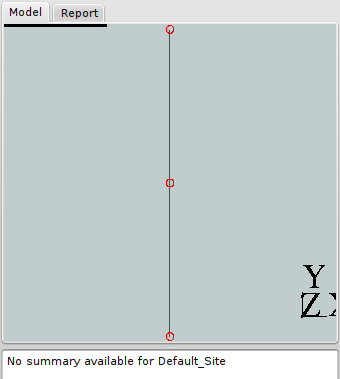
Now we can visualize “p1-p2”. To do so, click on “Process” in the toolbar or from the “Session” menu select “Process”. The message area should show the results of processing the session file. If all goes well, the last word in the message area should be “...Done!”. From the toolbar click on “Refresh” and voila! ...you should see a single line mark in the model viewer. From the “Model View” menu select “Single View” and “Top”. Then from the same menu area select “Center”. You should see something similar to Figure Model View 01. You may have to drag one of the sides of the model view window to force buildesui to center the view (this is an unfixed bug!). For the description of a line mark see lineMark section. Notice in the message window it says “No summary available for Default_Site”. This is because we are using the default site created by buildes. As we are not creating a building you can ignore this for this tutorial otherwise creating a site object will provide a more informative message. This is beyond the scope of this tutorial however.
Model View 01
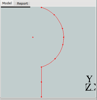
Next is the curve between the points p2 and p3. To accomplish this we need the distance between the two end points (p2 and p3) and the arc height (distance p2a and p2b). Enter the following lines to create an arc mark:
arcMark("p2-p3", 4000, 0, 1500, "r")
offset("p2-p3", "p1-p2_e")
Save and render your session file. Select the model view with your mouse and tap the “F” key on your keyboard to fit the adjusted model to your screen. Your view should be similar to Figure Model View 02. Again we have used the length and the angle of parts of the arc mark to provide buildes with the information to create it. Instead of the put command we have used offset. There is no difference between the two. The only reason for using it here is that it makes sense. The word “offset” signifies that we are manipulating one object based on another, while “put” does not. Otherwise you are free to use one or the other. So the offset line is telling buildes to place “p2-p3” by its first point on the same location as the end-point of “p1-p2”.
Model View 02
So far it has been easy enough to read the length for the marks in Figure 2D Outline with Coordinates but to create the line mark between p3 and p4 we need another way to make sure we have the accurate length. We shall use a point mark object. Enter the following lines to create the line mark between p3 and p4:
pointMark("p4")
put("p4", (-1000, 8000, 0))
lineMark("p3-p4")
offset("p3-p4", "p2-p3_e", "p4")
We have created a point mark object which we put at the coordinates for p4 (which we can easily read off the diagram). Then we create line mark without any parameters for length and angle which we do not know. Next we offset the new line mark object so that its first point is on the end point of the previous mark (“p2-p3”) and its length and direction will end up on the point mark “p4”. In effect what this has done is fit the new line mark between the two points designated by “p2-p3_e” and “p4”.
Complete the next two line marks with the following lines:
pointMark("p5")
put("p5", (3000, 10000, 0))
lineMark("p4-p5")
offset("p4-p5", "p3-p4_e", "p5")

pointMark("p6")
put("p5", (10000, 8000, 0))
lineMark("p5-p6")
offset("p5-p6", "p4-p5_e", "p6")
To create the arc mark between p6 and p7, we also have to use our “fit” technique. Use the following lines to accomplish this:
pointMark("p7")
offset("p7", (9000, 2000, 0))
arcMark("p6-p7", arcHeight=500, arcSide="r")
offset("p6-p7", "p5-p6_e", "p7")
Although we do not need to know the length or angle between the end points of the arc, we do have to know the height of the arc (i.e. distance between p6a and p6b which is 500 mm) and the side on which to create the curve which is “r” or “right”. Your model should look similar to Figure Model View 03.
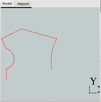
Model View 03
The line mark between p7 and p8 should be self explanatory. Note however that the last arc, unlike the two other arcs we have done so far, should have its arc on the left side of the chord. Creating the arc on the left is the default so we can omit the side designation. The following lines should complete the outline:
pointMark("p8")
offset("p8", (8000, 1000, 0))
lineMark("p7-p8")
offset("p7-p8", "p6-p7_e", "p8")

pointMark("p9")
offset("p9", (4000, 0, 0))
arcMark("p8-p9", arcHeight=1000)
offset("p8-p9", "p7-p8_e", "p9")

lineMark("p9-p10")
offset("p9-p10", "p8-p9_e", "p1-p2")
After centering and adjusting the figure to fit the screen, you should have a Figure similar to Model View 04. You can zoom window by pressing and holding the shift key while pressing the right mouse button. You can also drag the model view window by pressing and dragging using the middle mouse button.
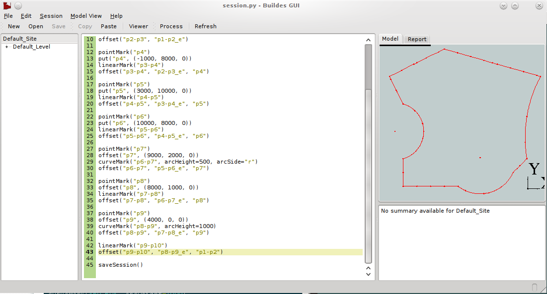
Model View 04
Browsing Marks
Buildes GUI allows the user to browse the modeled objects. To do this click on the “Default_Level” to expand it in the tree area. Select the object “p8-p9” with the left mouse button. The last arc is highlighted in the model view area. Also some information about the selected object is printed in the message window. From the printed information we can tell this object is an arc mark object. We can also see specific information about it such as its chord length and orientation. More interesting however is the number of marks as well as the interval for the last marker. This is useful information that can come in handy while creating new objects.